
ProsKit SS-331 desoldering gun and KSGER T12 controller
This is a post about tuning the KSGER T12 controller for use with the SS-331 desoldering gun. It’s reasonably accurate, but if you follow it, you do so at your own risk.
Problem
So‑called “affordable” desoldering guns are good enough. The SS‑331 may be “rather cheap” or “rather expensive”, but ultimately you want a compact unit with a normal handle for desoldering — ideally with a decent controller. Such options are expensive.
SS-331H handle
As of now, you can buy SS-331H handle separately. Though, there is not so much information about it from the first glance. So, pinout
- 1 - black - thermistor ground
- 2 - blue - thermistor signal
- 3 - red - heater ground
- 4 - red - heater VCC (24 V)
- 5, 6 - pump button pins
- 7 - yellow - reed switch
- green (to the case of the GX connector) - earth ground
The thermistor is about 47 ohms (around 47.8 ohms). Values may vary, so measure it yourself. The heater resistance is about 2 ohms and will increase (AFAIR up to 3.5 ohms) as it heats. What does this mean? With 24 V you will need a power supply that tolerates 12 A spikes. Or do as I did: use a 12 V power supply that can provide 8 A and stop worrying about burning outlets. Be aware that on startup you may see a spike of ~6 A, which quickly becomes 4–3 A after the initial heating. This spike can be enough to kill a weak supply. In short, take this one and forget about all these problems.
Short note about thermocouple vs thermistor
Same as me, you may not be familiar with all these “what’s the difference” notes. A thermocouple generates a small voltage — a few millivolts — by itself, without any power supply. A thermistor generates nothing; it just changes its resistance. Its readings are also usually rougher. This means that any circuit designed for a thermocouple will not work with a thermistor, simply because a thermocouple input expects a generated voltage while a thermistor provides none. To mimic a thermocouple’s behavior with a thermistor, you should do the following:
- Measure its resistance at 25 degrees Celsius
- Supply some voltage to the circuit (via an add‑on)
- Subtract from this voltage the voltage corresponding to the thermistor’s initial state
- Scale appropriately to mimic the thermocouple’s target voltage
Sounds complex, but in fact a single opamp is needed.
KSGER 2.1s module
Many people talk about different layouts, but currently you’ll find only one official one. It doesn’t have any zero‑ohm resistor or a special place to support JBL. So, you will need to perform the following changes:
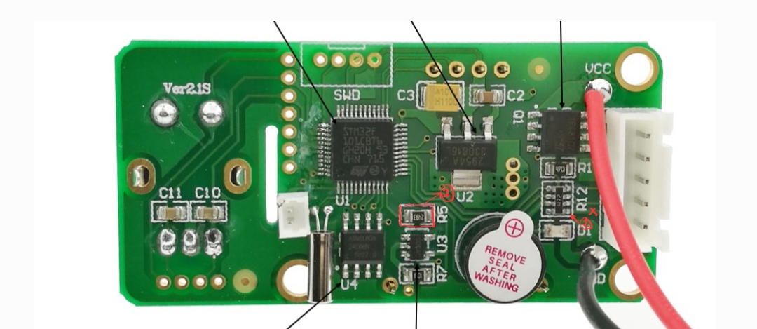
- Cut the trace at point one (lowest part of the resistor combo). This disconnects the thermocouple sensor from 24 V+.
- Remove the R5 resistor. It is responsible for amplifying the signal, and you will need to add a headcrab board at this spot to mimic a thermocouple with a thermistor.
From termoresistor to termocouple
You need the following headcrab schematic:

How does it work (to make things simple):
- You have two potentiometers that allow you to tune (a) the signal from the thermistor and (b) from the 47‑ohm reference resistor. The latter is used to subtract the thermistor’s initial resistance so the scale starts at zero.
- The op‑amp subtracts the signal from the 47‑ohm resistor from the thermistor signal.
- The op‑amp output is fed to U3 through point 1 on R12.
- Use the potentiometer on the left to tune the final amplification at U3.
- Use the 3.3 V rail from the display, for example.
Yes, of course, you probably can do this scheme much better. But I’m lazy and this way I could tune everything easily.
Headcrab calibration procedure
Some tips:
- Without a dedicated thermometer, you will burn something. Take one like this BEFORE YOU START.
- Without a current-limited supply you most probably will burn something again. Take one BEFORE YOU START.
- Get used to quick putting the KSGER controller to sleep / standby state. Do it fast.
- Or better make a resistor divider from 47 Ohm (0 C) to 150-156 Ohm (something around 400-420C for the gun heater). And first calibrate just the termoresistor reading with the heater disconnected. Yes, it works this way.
- “INVERT” message tells you about the negative voltage on U3 input. Don’t worry about it, though if you have it, you need to check voltages everywhere.
- Note that the resistance of the gun heater goes from 1.6 ohm in a cold state (room temperature) to around 3.5–4 ohms at 420 C. That means even if your 24 V supply works fine after you’ve already heated the gun to, say, 300 C, it may burn your controller when starting from cold due to a ~12 A spike.
- Note that temperature of the gun nozzle is DIFFERENT on it’s enclosure and on the tip. It’s DIFFERENT. Measure the one on the tip. ALWAYS.
The procedure (with resistor divider that mimic our termoresistor):
- Assemble headcrab and controller.
- Set your current-limited power supply to 12V.
- Connect 47ohm resistor to T+ and T-
- Set potentiometers to some value (better to, say, maximum value both)
- First, achieve a value close to zero at POINT 1 at room temperature. For that you should have equal values on T+ and the headcrab R5 output coming to the op‑amp. Don’t make these values less than 1 mV — too small. Don’t try to achieve a total zero at POINT 1 — set something like 0.3 mV. AFAIR I had ~5–6 mV on both. You may do better.
- Check that you have no INVERT message - turn it all off, turn it on again. If having INVERT, repeat the step 5.
- Check the displayed temperature. Tune RP3 to around 25–35 C.
- Turn the controller off.
- Connect 150-156 Ohm resistor to T+ and T-
- Tune RP3 to around 400–420 C.
- Re‑check with 47 ohm. If you get the same values as before, you’re fine. If not, find golden values — an initial value around 30–35 C and a maximum around 400 C.
- Turn the controller off.
- Connect termoresistor (1 and 2) respectively to T+ and T-.
- Connect 3 and 4 to the ground on your GX aviation connector and 4 to 12v on the same connector.
- Put your hand on the controller knob and be ready to immediately put it into sleep by quickly turning it left.
- Power everything on and put it to sleep state. If initial values are fine, continue. If not, find why not. Tip: if you have a floating ground like me, something like 100Ohm from the POINT 1 to ground will help you (though recalibration from the beginning will be needed probably).
- Set the target temperature to 150 C and start heating. Measure the temperature with your thermometer. If something goes wrong, stop, turn off, and rethink. Adjust RP3 along the way (very carefully). If all is OK, repeat for 300 C and 400 C (probably up to 350 C, since to achieve 400–420 you need something like 14 V on your power supply). Anyway, 350 C is totally fine.
- Put controller to sleep state, wait and see how the temperature goes down. The initial reading should be the same.
- Allow the gun to become cold and recalibrate if needed.
- Test, test, test — and be ready to turn everything off quickly at any step. Have I said this? Yes: please be ready for that. And make sure your power supply is either current‑limited or can handle up to 12 V / 6 A.
Pump
I took this one, you may find another. I connected it using a typical “MOSFET module with optocoupler” to save time (this one). Nobody knows how to trigger the controller to see the pump (even though it has a dedicated menu), but you don’t need it since the SS‑331 gun has a button for turning the pump on. Put it in series with the 3 V signal and you’re done.
Connector
AFAIK a GX connector with 7 pins is enough if you don’t want to add ambient temperature sensing. Otherwise you will have to change the default cable and re‑crimp (yep, re‑crimp, not resolder) it with the heater, and so on. I suggest not dealing with it — just skip ambient temperature. The tilt switch is already inside, though it works so‑so. But AFAIK the sleep mode turns on fine, so it works at least somehow.
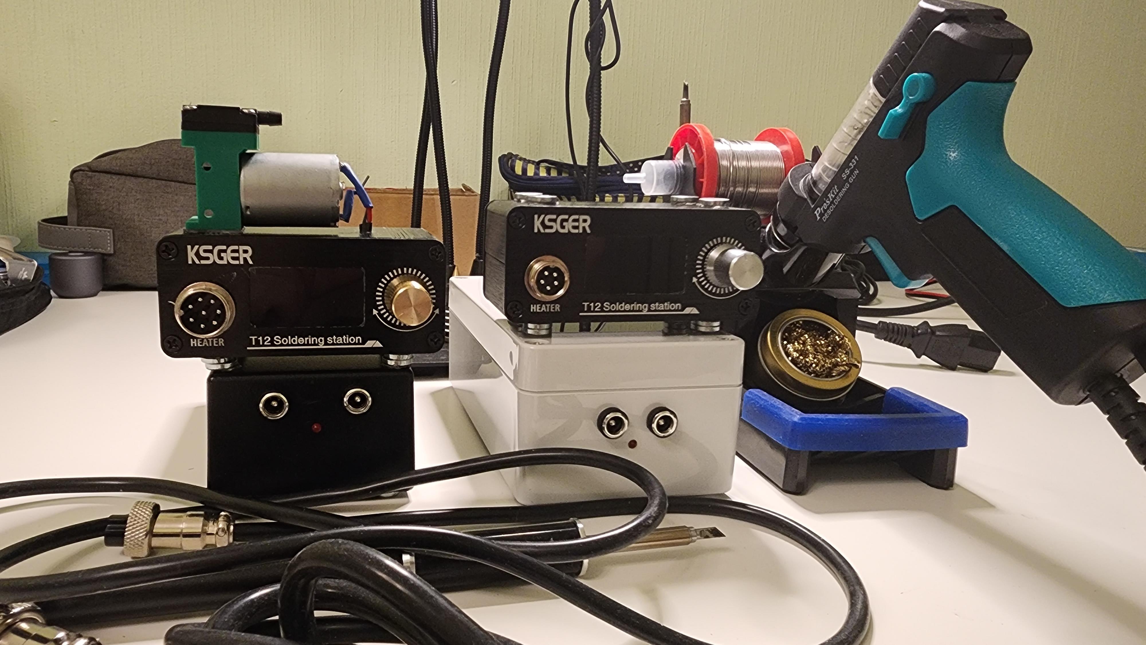
How does it look
Like this, and yes, it works fine:
Bonus
Temperature - resistance table:
| Temp | Ohms |
|---|---|
| 450 | 168 |
| 430 | 156 |
| 400 | 150 |
| 380 | 138 |
| 370 | 134 |
| 360 | 133 |
| 350 | 131 |
| 340 | 129 |
| 300 | 123 |
| 240 | 90 |
| 220 | 86 |
| 200 | 83 |
| 180 | 79 |
| 160 | 73 |
| 160 | 74 |
| 150 | 72 |
| 140 | 70 |
| 130 | 68 |
| 119 | 66 |
| 100 | 63 |
| 80 | 59 |
| 70 | 57 |
| 50 | 53 |